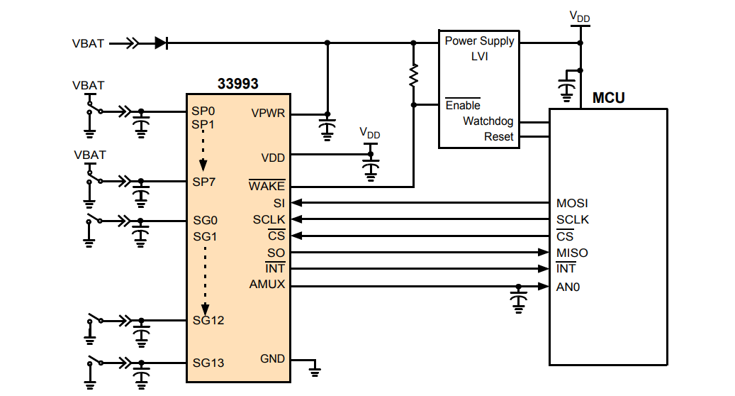
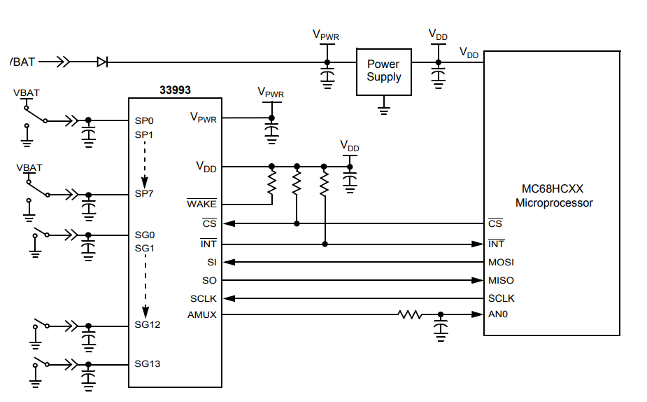
The multi-switch detection interface is designed to detect the closing and opening of up to 22 switch contacts. The switching state, on or off, is transmitted to the microprocessor unit (MCU) via the Serial Peripheral Interface (SPI). The device also has a 22-to-1 analog multiplexer for reading analog inputs. The analog input signal is buffered and provided on the AMUX output pin for the MCU to read.
The 33993 device has two operating modes, Sleep and Normal. The sleep mode provides low static current, enabling the device to wake up. Normal mode allows the device to be programmed and provides a pull-up or pull-down current for switch contacts as it monitors changes in switch state.
MC33993 Simplified application diagram
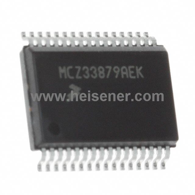
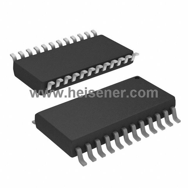
33993 adopts 32-pin wide-body SOIC package to reduce the area of the circuit board. The low rest current makes the 33993 ideal for automobiles and industrial products that require low sleep state current
Internal block diagram

The 33993 provides a WAKE output and wake input to control the enable pins on the system power supply. In normal mode, if the output of WAKE is low, power is enabled. In Sleep mode, pin WAKE high and power off. The WAKE pin has a passive pull-up to the internal 5.0V power supply, but can be pull-up to the VPWR power supply via a resistor
Power off in sleep mode

When the WAKE output is not in use, the pin should be pulled through the resistor to the VDD power supply.In sleep mode, the switch closing will set the WAKE pin to low, causing 33993 to enter normal mode. The power supply will be activated to power the VDD pins, microprocessor, and 33993. The microprocessor can determine the wake source by reading the interrupt flag.
Power activation in sleep mode
Features
• Designed to run 5.5V ≤VPWR≤26v
• Switch input voltage range -14 V to VPWR, maximum 40 V
• Interface directly to microprocessor using 3.3V / 5.0V SPI agreement
• Optional changes to wake status
• Optional wetting current (16 mA or 2.0 mA)
• 8 programmable inputs (battery or ground switch)
• 14 switches for ground input
• VPWR Standby Current 100 μA Typical, VDD Standby Current 20 μA Typical
• Active interrupt (INT) when switch state changes
• Lead-free packaging specifies suffix code EW